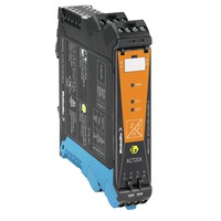
Ex valve control modules, 60 mA ignition protection group IIB 1-channel valve control modules in 22.5 mm width with external power supply, to control valves in Ex areas zone 0,1,2 from the safe zone. The module comes with full three-way, 2.6 kV separation. On the input side, NPN/PNP switching sensors can be connected. On the output side, there are three 60 mA driver steps for ignition protection group IIB with a minimum driver voltage of 9 V/11 V or 12.5 V available optionally. An additional alarm contact ("a" contact) reports status and error messages The module can be configured using standard FDT/DTM software.
Add-on housing for TS35 DIN rail installation Dimensions: L/W/H 119.2/ 22.5/ 113.6 Screw connection/ nominal cross-section 2.5 mm2 Protection degree: IP20 input NPN, PNP switch signal max. 28 VDC output Ex Imax 60 mA @ ignition protection group IIB U with load min. 9 V / min. 11 V / min. 12.5 V U without load min. 24 V Alarm output relay 1 NO contact 250 VAC / 30 VDC @ 2A safe zone 32 VAC @ 0.5 A / 32 VDC @ 1 A zone 2Auxiliary power 19 to 31.2 VDCPower loss approx. 1.8 W Ambienttemperature range -20 °C to +60 °C
Secure isolation EN 61010, 3-way isolation up to 2.6 kV AC/DC of all circuits against each other Working voltage 300 V AC/DC at overvoltage category II and pollution degree 2 Approvals cULus, ATEX IECEX, FM
ATEX marking II 3 G Ex nA nC IIC T4 ATEX characteristic data U0 = 28 V DC I0 = 125 mA P0 = 0.77 W TypeACT20X-SDI-HDO-H-S
Short specification
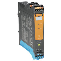
Ex valve control modules, 60 mA ignition protection group IIB 1-channel valve control modules in 22.5 mm width with external power supply, to control valves in Ex zones 0,1,2 from the safe zone. The module comes with full three-way, 2.6 kV separation. On the input side, NPN/PNP switching sensors can be connected. On the output side, there are three 60 mA driver steps for ignition protection group IIB with a minimum driver voltage of 9 V/11 V or 12.5 V available optionally. An additional alarm contact ("a" contact) reports status and error messages The module can be configured using standard FDT/DTM software.
Ex valve control modules, 60 mA ignition protection group IIB 1-channel valve control modules in 22.5 mm width with external power supply, to control valves in Ex areas zone 0,1,2 from the safe zone. The module comes with full three-way, 2.6 kV separation. On the input side, NPN/PNP switching sensors can be connected. On the output side, there are three 60 mA driver steps for ignition protection group IIB with a minimum driver voltage of 9 V/11 V or 12.5 V available optionally. An additional alarm contact ("a" contact) reports status and error messages The module can be configured using standard FDT/DTM software.
Add-on housing for TS35 DIN rail installation Dimensions: L/W/H 119.2/ 22.5/ 113.6 Screw connection/ nominal cross-section 2.5 mm2 Protection degree: IP20 input NPN, PNP switch signal max. 28 VDC output Ex Imax 60 mA @ ignition protection group IIB U with load min. 9 V / min. 11 V / min. 12.5 V U without load min. 24 V Alarm output relay 1 NO contact 250 VAC / 30 VDC @ 2A safe zone 32 VAC @ 0.5 A / 32 VDC @ 1 A zone 2Auxiliary power 19 to 31.2 VDCPower loss approx. 1.8 W Ambienttemperature range -20 °C to +60 °C
Secure isolation EN 61010, 3-way isolation up to 2.6 kV AC/DC of all circuits against each other Working voltage 300 V AC/DC at overvoltage category II and pollution degree 2 Approvals cULus, ATEX IECEX, FM
ATEX marking II 3 G Ex nA nC IIC T4 ATEX characteristic data U0 = 28 V DC I0 = 125 mA P0 = 0.77 W TypeACT20X-SDI-HDO-H-S
Short specification
Ex valve control modules, 60 mA ignition protection group IIB 1-channel valve control modules in 22.5 mm width with external power supply, to control valves in Ex zones 0,1,2 from the safe zone. The module comes with full three-way, 2.6 kV separation. On the input side, NPN/PNP switching sensors can be connected. On the output side, there are three 60 mA driver steps for ignition protection group IIB with a minimum driver voltage of 9 V/11 V or 12.5 V available optionally. An additional alarm contact ("a" contact) reports status and error messages The module can be configured using standard FDT/DTM software.
This function is provided via the external service provider https://supplyframe.com. By clicking on "Continue" you will be redirected to this page. This leads to a data transfer of personal data to non-European countries. Please check the data protection policy of the external website, for which Weidmüller assumes no responsibility and liability.


;)


;)
;)
;)
;)
;)