Length of ferrules is to be chosen depending on the product and the rated voltage., The outside diameter of the plastic collar should not be larger than the pitch (P)
Rated data acc. to IEC
tested acc. to standard
IEC 60664-1, IEC 61984
Rated current, min. number of poles (Tu=20°C)
24 A
Rated current, max. number of poles (Tu=20°C)
24 A
Rated current, min. number of poles (Tu=40°C)
24 A
Rated current, max. number of poles (Tu=40°C)
24 A
Rated voltage for surge voltage class / pollution degree II/2
1,000 V
Rated voltage for surge voltage class / pollution degree III/2
800 V
Rated voltage for surge voltage class / pollution degree III/3
400 V
Rated impulse voltage for surge voltage class/ pollution degree II/2
6 kV
Rated impulse voltage for surge voltage class/ pollution degree III/2
6 kV
Rated impulse voltage for surge voltage class/ contamination degree III/3
6 kV
Rated data acc. to CSA
Rated voltage (Use group B / CSA)
300 V
Rated voltage (Use group C / CSA)
150 V
Rated voltage (Use group D / CSA)
300 V
Rated current (Use group B / CSA)
15 A
Rated current (Use group C / CSA)
15 A
Rated current (Use group D / CSA)
10 A
Wire cross-section, AWG, min.
AWG 26
Wire cross-section, AWG, max.
AWG 14
Rated data acc. to UL 1059
Institute (cURus)
Certificate No. (cURus)
E60693
Rated voltage (Use group B / UL 1059)
300 V
Rated voltage (Use group C / UL 1059)
150 V
Rated voltage (Use group D / UL 1059)
300 V
Rated current (Use group B / UL 1059)
15 A
Rated current (Use group C / UL 1059)
15 A
Rated current (Use group D / UL 1059)
10 A
Wire cross-section, AWG, min.
AWG 26
Wire cross-section, AWG, max.
AWG 14
Reference to approval values
Specifications are maximum values, details - see approval certificate.
Packing
Packaging
Box
VPE length
0
VPE width
0
VPE height
0
Type tests
Test: Durability of markings
Test
mark of origin, type identification, type of material, approval marking UL, approval marking CSA, durability
Evaluation
available
Test: Clampable cross section
Standard
DIN EN 60999-1 section 7 and 9.1 / 12.00, DIN EN 60947-1 section 8.2.4.5.1 / 12.02
Conductor type
Type of conductor and conductor cross-section
solid 0.14 mm²
Type of conductor and conductor cross-section
stranded 0.14 mm²
Type of conductor and conductor cross-section
solid 2.5 mm²
Type of conductor and conductor cross-section
stranded 2.5 mm²
Type of conductor and conductor cross-section
AWG 26/1
Type of conductor and conductor cross-section
AWG 26/19
Type of conductor and conductor cross-section
AWG 14/1
Type of conductor and conductor cross-section
AWG 14/19
Evaluation
passed
Test for damage to and accidental loosening of conductors
Standard
DIN EN 60999-1 section 9.4 / 12.00
Requirement
0.2 kg
Conductor type
Type of conductor and conductor cross-section
AWG 26/1
Type of conductor and conductor cross-section
AWG 26/19
Evaluation
passed
Requirement
0.3 kg
Conductor type
Type of conductor and conductor cross-section
solid 0.5 mm²
Type of conductor and conductor cross-section
stranded 0.5 mm²
Evaluation
passed
Requirement
0.7 kg
Conductor type
Type of conductor and conductor cross-section
solid 2.5 mm²
Type of conductor and conductor cross-section
stranded 2.5 mm²
Evaluation
passed
Requirement
0.9 kg
Conductor type
Type of conductor and conductor cross-section
AWG 14/1
Type of conductor and conductor cross-section
AWG 14/19
Evaluation
passed
Pull-out test
Standard
DIN EN 60999-1 section 9.5 / 12.00
Requirement
≥10 N
Conductor type
Type of conductor and conductor cross-section
AWG 26/1
Type of conductor and conductor cross-section
AWG 26/19
Evaluation
passed
Requirement
≥20 N
Conductor type
Type of conductor and conductor cross-section
H05V-U0.5
Type of conductor and conductor cross-section
H05V-K0.5
Evaluation
passed
Requirement
≥50 N
Conductor type
Type of conductor and conductor cross-section
H07V-U2.5
Type of conductor and conductor cross-section
H07V-K2.5
Type of conductor and conductor cross-section
AWG 14/1
Type of conductor and conductor cross-section
AWG 14/19
Evaluation
passed
Important note
IPC conformity
Conformity: The products are developed, manufactured and delivered according international recognized standards and norms and comply with the assured properties in the data sheet resp. fulfill decorative properties in accordance with IPC-A-610 "Class 2". Further claims on the products can be evaluated on request.
Notes
Rated current related to rated cross-section & min. No. of poles.
Wire end ferrule without plastic collar to DIN 46228/1
Wire end ferrule with plastic collar to DIN 46228/4
P on drawing = pitch
Rated data refer only to the component itself. Clearance and creepage distances to other components are to be designed in accordance with the relevant application standards.
Long term storage of the product with average temperature of 50 °C and maximum humidity 70%, 36 months
Length of ferrules is to be chosen depending on the product and the rated voltage., The outside diameter of the plastic collar should not be larger than the pitch (P)
Conformity: The products are developed, manufactured and delivered according international recognized standards and norms and comply with the assured properties in the data sheet resp. fulfill decorative properties in accordance with IPC-A-610 "Class 2". Further claims on the products can be evaluated on request.
Notes
Rated current related to rated cross-section & min. No. of poles.
Wire end ferrule without plastic collar to DIN 46228/1
Wire end ferrule with plastic collar to DIN 46228/4
P on drawing = pitch
Rated data refer only to the component itself. Clearance and creepage distances to other components are to be designed in accordance with the relevant application standards.
Long term storage of the product with average temperature of 50 °C and maximum humidity 70%, 36 months
This function is provided via the external service provider https://supplyframe.com. By clicking on "Continue" you will be redirected to this page. This leads to a data transfer of personal data to non-European countries. Please check the data protection policy of the external website, for which Weidmüller assumes no responsibility and liability.


: 3.5 mm, tinned, Pale green, Tension-clamp connection, Clamping range, max. : 2.5 mm², Box',1,'100.0',1,'19525800009999.jpg',false,0);)


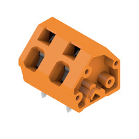
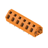
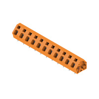
: 3.5 mm, tinned, orange, Tension-clamp connection, Clamping range, max. : 2.5 mm², Box',1,'100.0',1,'1952570000_iso_bottom.jpg',false,0);)
: 3.5 mm, tinned, orange, Tension-clamp connection, Clamping range, max. : 2.5 mm², Box',1,'100.0',1,'1952570000_iso_bottom.jpg',true,5);)
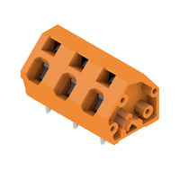
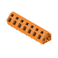
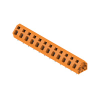
: 3.5 mm, tinned, orange, Tension-clamp connection, Clamping range, max. : 2.5 mm², Box',1,'100.0',1,'1952580000_iso_bottom.jpg',false,0);)
: 3.5 mm, tinned, orange, Tension-clamp connection, Clamping range, max. : 2.5 mm², Box',1,'100.0',1,'1952580000_iso_bottom.jpg',true,5);)
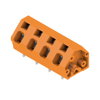
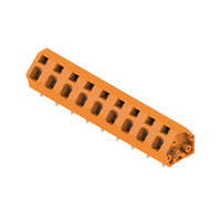
: 3.5 mm, tinned, orange, Tension-clamp connection, Clamping range, max. : 2.5 mm², Box',1,'100.0',1,'1952590000_iso_bottom.jpg',false,0);)
: 3.5 mm, tinned, orange, Tension-clamp connection, Clamping range, max. : 2.5 mm², Box',1,'100.0',1,'1952590000_iso_bottom.jpg',true,5);)
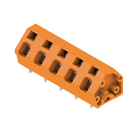
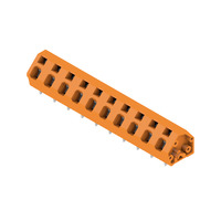
: 3.5 mm, tinned, orange, Tension-clamp connection, Clamping range, max. : 2.5 mm², Box',1,'100.0',1,'1952600000_iso_bottom.jpg',false,0);)
: 3.5 mm, tinned, orange, Tension-clamp connection, Clamping range, max. : 2.5 mm², Box',1,'100.0',1,'1952600000_iso_bottom.jpg',true,5);)
: 3.5 mm, tinned, orange, Tension-clamp connection, Clamping range, max. : 2.5 mm², Box',1,'100.0',1,'1952610000_iso_bottom.jpg',false,0);)
: 3.5 mm, tinned, orange, Tension-clamp connection, Clamping range, max. : 2.5 mm², Box',1,'100.0',1,'1952620000_iso_bottom.jpg',false,0);)
: 3.5 mm, tinned, orange, Tension-clamp connection, Clamping range, max. : 2.5 mm², Box',1,'100.0',1,'1952630000_iso_bottom.jpg',false,0);)
: 3.5 mm, tinned, orange, Tension-clamp connection, Clamping range, max. : 2.5 mm², Box',1,'100.0',1,'1952640000_iso_bottom.jpg',false,0);)
: 3.5 mm, tinned, orange, Tension-clamp connection, Clamping range, max. : 2.5 mm², Box',1,'100.0',1,'1952650000_iso_bottom.jpg',false,0);)
: 3.5 mm, tinned, orange, Tension-clamp connection, Clamping range, max. : 2.5 mm², Box',1,'100.0',1,'1952660000_iso_bottom.jpg',false,0);)
: 3.5 mm, tinned, orange, Tension-clamp connection, Clamping range, max. : 2.5 mm², Box',1,'100.0',1,'1952670000_iso_bottom.jpg',false,0);)