Connectivity
Electronics
Automation & Software
Workplace & Accessories
Assembly
Terminal Blocks
Connectors
PCB Terminals and Connectors
Enclosure Systems and Components
Contactless Connectivity
Cable Entry Systems and Components
Cord sets, Patchcords and Cables
PLC Interfaces and Migration Solutions
Service Interfaces
Distribution Boxes
OMNIMATE 4.0
OMNIMATE Data PCB connectors
PCB terminals - OMNIMATE Signal
PCB connectors - OMNIMATE Signal
PCB terminals - OMNIMATE Power
PCB connectors - OMNIMATE Power
Feedthrough terminals for devices - OMNIMATE Power
PCB circular connectors - IP67
Sample set - OMNIMATE
Clamping yoke screw connection
PUSH IN spring connection
6 mm² (AWG 10) - pitch 6.35 mm - LL 6.35
16 mm² (AWG 6) - Pitch 10.16 mm - LU 10.16
16 mm² (AWG 6) - Pitch 10.16 mm - LUP 10.16 with test point
16 mm² (AWG 6) - Pitch 12.70 mm - LUP 12.70 with test point
25 mm² (AWG 4) - Pitch 15.00 mm - LX 15.00 with test point
50 mm² (AWG 1) - pitch 15.00 mm - LXXX 15.00 with test point
LU 10.16/90
LU 10.16/03/90 4.5SN GY BX PRT
General ordering data
Version
Printed circuit board terminals, 10.16 mm, Number of poles: 3, 90°, Solder pin length (l): 4.5 mm, tinned, Pebble grey, Clamping yoke connection, Clamping range, max. : 16 mm², Box
Order No.
1812250000
Type
LU 10.16/03/90 4.5SN GY BX PRT
GTIN (EAN)
4032248291502
Qty.
20 pc(s).
Product data
IEC: 1000 V / 76 A / 0.5 - 16 mm²
Packaging
Box
Dimensions and weights
Depth
18.3 mm
Depth (inches)
0.72 inch
Height
33 mm
Height (inches)
1.299 inch
Height of lowest version
28.5 mm
Width
30.48 mm
Width (inches)
1.2 inch
Net weight
28.6 g
Environmental Product Compliance
RoHS Compliance Status
Compliant without exemption
REACH SVHC
/
System parameters
Product family
OMNIMATE Power - series LU
Wire connection method
Clamping yoke connection
Mounting onto the PCB
THT solder connection
Conductor outlet direction
90°
Pitch in mm (P)
10.16 mm
Pitch in inches (P)
0.4 "
Number of poles
3
Pin series quantity
1
Fitted by customer
Yes
Number of rows
1
Max. adjacent poles per row
10
Solder pin length (l)
4.5 mm
Solder pin dimensions
1.2 x 1.2 mm
Solder pin dimensions = d tolerance
0 / -0,15 mm
Solder eyelet hole diameter (D)
1.6 mm
Solder eyelet hole diameter tolerance (D)
+ 0,1 mm
Number of solder pins per pole
2
Screwdriver blade
1.0 x 5.5
Screwdriver blade standard
DIN 5264
Tightening torque, min.
1.2 Nm
Tightening torque, max.
2.2 Nm
Clamping screw
M 4
Stripping length
12 mm
L1 in mm
20.32 mm
L1 in inches
0.8 "
Touch-safe protection acc. to DIN VDE 0470
IP20 plugged/ IP10 unplugged
Touch-safe protection acc. to DIN VDE 57 106
Safe from finger touch
Protection degree
IP20
Volume resistance
0.50 mΩ
Material data
Insulating material
Wemid (PA)
Colour
Pebble grey
Colour chart (similar)
RAL 7032
Insulating material group
I
Comparative Tracking Index (CTI)
≥ 600
UL 94 flammability rating
V-0
Contact material
Cu-alloy
Contact surface
tinned
Layer structure of solder connection
1.5...3 µm Ni / 4...6 µm Sn matt
Storage temperature, min.
-40 °C
Storage temperature, max.
70 °C
Operating temperature, min.
-50 °C
Operating temperature, max.
120 °C
Temperature range, installation, min.
-25 °C
Temperature range, installation, max.
120 °C
Conductors suitable for connection
Clamping range, min.
0.14 mm²
Clamping range, max.
16 mm²
Wire connection cross section AWG, min.
AWG 22
Wire connection cross section AWG, max.
AWG 8
Solid, min. H05(07) V-U
0.5 mm²
Solid, max. H05(07) V-U
16 mm²
Stranded, min. H07V-R
6 mm²
Stranded, max. H07V-R
16 mm²
Flexible, min. H05(07) V-K
0.5 mm²
Flexible, max. H05(07) V-K
16 mm²
w. plastic collar ferrule, DIN 46228 pt 4, min.
2.5 mm²
w. plastic collar ferrule, DIN 46228 pt 4, max.
10 mm²
w. wire end ferrule, DIN 46228 pt 1, min.
2.5 mm²
w. wire end ferrule, DIN 46228 pt 1, max.
10 mm²
Plug gauge in accordance with EN 60999 a x b; ø
5.4 mm x 5.1 mm; 5.3 mm
Clampable conductor
Cross-section for conductor connection
Type
fine-wired
nominal
2.5 mm²
wire end ferrule
Stripping length
Recommended wire-end ferrule
H2,5/12
Stripping length
Recommended wire-end ferrule
H2,5/19D BL
Cross-section for conductor connection
Type
fine-wired
nominal
4 mm²
wire end ferrule
Stripping length
Recommended wire-end ferrule
H4,0/12
Stripping length
Recommended wire-end ferrule
H4,0/20D GR
Cross-section for conductor connection
Type
fine-wired
nominal
6 mm²
wire end ferrule
Stripping length
Recommended wire-end ferrule
H6,0/12
Stripping length
Recommended wire-end ferrule
H6,0/20 SW
Cross-section for conductor connection
Type
fine-wired
nominal
10 mm²
wire end ferrule
Stripping length
Recommended wire-end ferrule
H10,0/22 EB
Stripping length
Recommended wire-end ferrule
H10,0/12
Reference text
Length of ferrules is to be chosen depending on the product and the rated voltage., The outside diameter of the plastic collar should not be larger than the pitch (P)
Rated data acc. to IEC
tested acc. to standard
IEC 60664-1, IEC 61984
Rated current, min. number of poles (Tu=20°C)
76 A
Rated current, max. number of poles (Tu=20°C)
72 A
Rated current, min. number of poles (Tu=40°C)
76 A
Rated current, max. number of poles (Tu=40°C)
62 A
Rated voltage for surge voltage class / pollution degree II/2
1,000 V
Rated voltage for surge voltage class / pollution degree III/2
690 V
Rated voltage for surge voltage class / pollution degree III/3
690 V
Rated impulse voltage for surge voltage class/ pollution degree II/2
4 kV
Rated impulse voltage for surge voltage class/ pollution degree III/2
6 kV
Rated impulse voltage for surge voltage class/ contamination degree III/3
6 kV
Short-time withstand current resistance
2 x 1s with 700 A
Rated data acc. to CSA
Institute (CSA)
Certificate No. (CSA)
200039-1198743
Rated voltage (Use group B / CSA)
300 V
Rated voltage (Use group C / CSA)
150 V
Rated voltage (Use group D / CSA)
300 V
Rated current (Use group B / CSA)
65 A
Rated current (Use group C / CSA)
65 A
Rated current (Use group D / CSA)
10 A
Wire cross-section, AWG, min.
AWG 22
Wire cross-section, AWG, max.
AWG 6
Reference to approval values
Specifications are maximum values, details - see approval certificate.
Rated data acc. to UL 1059
Institute (UR)
Certificate No. (UR)
E60693
Rated voltage (Use group B / UL 1059)
300 V
Rated voltage (Use group C / UL 1059)
150 V
Rated voltage (Use group D / UL 1059)
600 V
Rated current (Use group B / UL 1059)
65 A
Rated current (Use group C / UL 1059)
65 A
Rated current (Use group D / UL 1059)
5 A
Wire cross-section, AWG, min.
AWG 26
Wire cross-section, AWG, max.
AWG 6
Reference to approval values
Specifications are maximum values, details - see approval certificate.
Packing
Packaging
Box
VPE length
141 mm
VPE width
105 mm
VPE height
40 mm
Type tests
Test: Durability of markings
Test
mark of origin, type identification, type of material, rated cross-section, approval marking CSA, approval marking UL, pitch, durability
Evaluation
available
Test: Clampable cross section
Standard
EN 60999/1993
Conductor type
Type of conductor and conductor cross-section
H05V-K0.5
Type of conductor and conductor cross-section
H05V-U0.5
Type of conductor and conductor cross-section
H07V-K10
Type of conductor and conductor cross-section
H07V-U10
Type of conductor and conductor cross-section
H07V-U16
Type of conductor and conductor cross-section
AWG8/7
Type of conductor and conductor cross-section
AWG 8/19
Type of conductor and conductor cross-section
AWG 22/1
Type of conductor and conductor cross-section
AWG 22/19
Evaluation
passed
Test for damage to and accidental loosening of conductors
Standard
EN 60947-1/1991 section 8.2.4.3
Requirement
0.3 kg
Conductor type
Type of conductor and conductor cross-section
H05V-K0.5
Type of conductor and conductor cross-section
H05V-U0.5
Type of conductor and conductor cross-section
AWG 22/1
Type of conductor and conductor cross-section
AWG 22/19
Evaluation
passed
Requirement
2.0 kg
Conductor type
Type of conductor and conductor cross-section
H07V-K10
Type of conductor and conductor cross-section
H07V-U10
Type of conductor and conductor cross-section
AWG8/7
Type of conductor and conductor cross-section
AWG 8/19
Evaluation
passed
Requirement
2.9 kg
Conductor type
Type of conductor and conductor cross-section
H07V-U16
Evaluation
passed
Pull-out test
Standard
EN 60947-1/1991 section 8.2.4.4
Requirement
≥20 N
Conductor type
Type of conductor and conductor cross-section
AWG 22/1
Type of conductor and conductor cross-section
AWG 22/19
Evaluation
passed
Requirement
≥30 N
Conductor type
Type of conductor and conductor cross-section
H05V-K0.5
Type of conductor and conductor cross-section
H05V-U0.5
Evaluation
passed
Requirement
≥ 90N
Conductor type
Type of conductor and conductor cross-section
H07V-K10
Type of conductor and conductor cross-section
H07V-U10
Type of conductor and conductor cross-section
AWG8/7
Type of conductor and conductor cross-section
AWG 8/19
Evaluation
passed
Requirement
≥100 N
Conductor type
Type of conductor and conductor cross-section
H07V-U16
Evaluation
passed
Important note
IPC conformity
Conformity: The products are developed, manufactured and delivered according international recognized standards and norms and comply with the assured properties in the data sheet resp. fulfill decorative properties in accordance with IPC-A-610 "Class 2". Further claims on the products can be evaluated on request.
Notes
Long term storage of the product with average temperature of 50 °C and maximum humidity 70%, 36 months
Downloads
Approval/Certificate/Document of Conformity
Product Change Notification
User Documentation
Catalogues
Catalogues in PDF-format
Brochures
Classifications
ETIM 6.0
EC002643
ETIM 7.0
EC002643
ETIM 8.0
EC002643
ETIM 9.0
EC002643
ECLASS 9.0
27-44-04-01
ECLASS 9.1
27-44-04-01
ECLASS 10.0
27-44-04-01
ECLASS 11.0
27-46-01-01
ECLASS 12.0
27-46-01-01
ECLASS 13.0
27-46-01-01
ECLASS 14.0
27-46-01-01
Approvals
Approvals
ROHS
Conform
UL File Number Search
UL Website
Certificate No. (UR)
E60693
Show all
2
3
4
5
6
7
8
9
10
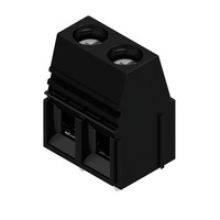
Number of poles:
2
Order No.:
1934140000
Type:
LU 10.16/02/90 4.5SN BK BX
Colour:
black
Solder pin length (l):
4.5 mm
Version:
Printed circuit board terminals, 10.16 mm, Number of poles: 2, 90°, Solder pin length (l): 4.5 mm, tinned, black, Clamping yoke connection, Clamping range, max. : 16 mm², Box
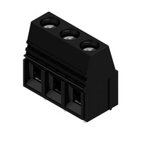
Number of poles:
3
Order No.:
1921450000
Type:
LU 10.16/03/90 4.5SN BK BX
Colour:
black
Solder pin length (l):
4.5 mm
Version:
Printed circuit board terminals, 10.16 mm, Number of poles: 3, 90°, Solder pin length (l): 4.5 mm, tinned, black, Clamping yoke connection, Clamping range, max. : 16 mm², Box
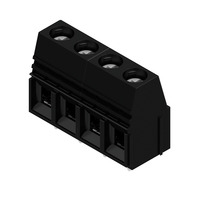
Number of poles:
4
Order No.:
1226220000
Type:
LU 10.16/04/90 4.5SN BK BX
Colour:
black
Solder pin length (l):
4.5 mm
Version:
Printed circuit board terminals, 10.16 mm, Number of poles: 4, 90°, Solder pin length (l): 4.5 mm, tinned, black, Clamping yoke connection, Clamping range, max. : 16 mm², Box
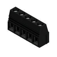
Number of poles:
5
Order No.:
1226230000
Type:
LU 10.16/05/90 4.5SN BK BX
Colour:
black
Solder pin length (l):
4.5 mm
Version:
Printed circuit board terminals, 10.16 mm, Number of poles: 5, 90°, Solder pin length (l): 4.5 mm, tinned, black, Clamping yoke connection, Clamping range, max. : 16 mm², Box
Number of poles:
6
Order No.:
1226240000
Type:
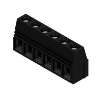
LU 10.16/06/90 4.5SN BK BX
Colour:
black
Solder pin length (l):
4.5 mm
Version:
Printed circuit board terminals, 10.16 mm, Number of poles: 6, 90°, Solder pin length (l): 4.5 mm, tinned, black, Clamping yoke connection, Clamping range, max. : 16 mm², Box
Number of poles:
7
Order No.:
1226250000
Type:
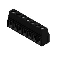
LU 10.16/07/90 4.5SN BK BX
Colour:
black
Solder pin length (l):
4.5 mm
Version:
Printed circuit board terminals, 10.16 mm, Number of poles: 7, 90°, Solder pin length (l): 4.5 mm, tinned, black, Clamping yoke connection, Clamping range, max. : 16 mm², Box
Number of poles:
8
Order No.:
1226260000
Type:
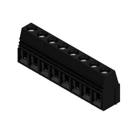
LU 10.16/08/90 4.5SN BK BX
Colour:
black
Solder pin length (l):
4.5 mm
Version:
Printed circuit board terminals, 10.16 mm, Number of poles: 8, 90°, Solder pin length (l): 4.5 mm, tinned, black, Clamping yoke connection, Clamping range, max. : 16 mm², Box
Number of poles:
9
Order No.:
1226270000
Type:
LU 10.16/09/90 4.5SN BK BX
Colour:
black
Solder pin length (l):
4.5 mm
Version:
Printed circuit board terminals, 10.16 mm, Number of poles: 9, 90°, Solder pin length (l): 4.5 mm, tinned, black, Clamping yoke connection, Clamping range, max. : 16 mm², Box
Number of poles:
10
Order No.:
1226280000
Type:
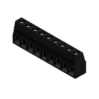
LU 10.16/10/90 4.5SN BK BX
Colour:
black
Solder pin length (l):
4.5 mm
Version:
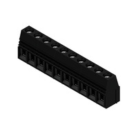
Printed circuit board terminals, 10.16 mm, Number of poles: 10, 90°, Solder pin length (l): 4.5 mm, tinned, black, Clamping yoke connection, Clamping range, max. : 16 mm², Box
Version
Printed circuit board terminals, 10.16 mm, Number of poles: 3, 90°, Solder pin length (l): 4.5 mm, tinned, Pebble grey, Clamping yoke connection, Clamping range, max. : 16 mm², Box
Order No.
1812250000
Type
LU 10.16/03/90 4.5SN GY BX PRT
GTIN (EAN)
4032248291502
Qty.
20 pc(s).
Product data
IEC: 1000 V / 76 A / 0.5 - 16 mm²
Packaging
Box
Depth
18.3 mm
Depth (inches)
0.72 inch
Height
33 mm
Height (inches)
1.299 inch
Height of lowest version
28.5 mm
Width
30.48 mm
Width (inches)
1.2 inch
Net weight
28.6 g
RoHS Compliance Status
Compliant without exemption
REACH SVHC
/
Product family
OMNIMATE Power - series LU
Wire connection method
Clamping yoke connection
Mounting onto the PCB
THT solder connection
Conductor outlet direction
90°
Pitch in mm (P)
10.16 mm
Pitch in inches (P)
0.4 "
Number of poles
3
Pin series quantity
1
Fitted by customer
Yes
Number of rows
1
Max. adjacent poles per row
10
Solder pin length (l)
4.5 mm
Solder pin dimensions
1.2 x 1.2 mm
Solder pin dimensions = d tolerance
0 / -0,15 mm
Solder eyelet hole diameter (D)
1.6 mm
Solder eyelet hole diameter tolerance (D)
+ 0,1 mm
Number of solder pins per pole
2
Screwdriver blade
1.0 x 5.5
Screwdriver blade standard
DIN 5264
Tightening torque, min.
1.2 Nm
Tightening torque, max.
2.2 Nm
Clamping screw
M 4
Stripping length
12 mm
L1 in mm
20.32 mm
L1 in inches
0.8 "
Touch-safe protection acc. to DIN VDE 0470
IP20 plugged/ IP10 unplugged
Touch-safe protection acc. to DIN VDE 57 106
Safe from finger touch
Protection degree
IP20
Volume resistance
0.50 mΩ
Insulating material
Wemid (PA)
Colour
Pebble grey
Colour chart (similar)
RAL 7032
Insulating material group
I
Comparative Tracking Index (CTI)
≥ 600
UL 94 flammability rating
V-0
Contact material
Cu-alloy
Contact surface
tinned
Layer structure of solder connection
1.5...3 µm Ni / 4...6 µm Sn matt
Storage temperature, min.
-40 °C
Storage temperature, max.
70 °C
Operating temperature, min.
-50 °C
Operating temperature, max.
120 °C
Temperature range, installation, min.
-25 °C
Temperature range, installation, max.
120 °C
Clamping range, min.
0.14 mm²
Clamping range, max.
16 mm²
Wire connection cross section AWG, min.
AWG 22
Wire connection cross section AWG, max.
AWG 8
Solid, min. H05(07) V-U
0.5 mm²
Solid, max. H05(07) V-U
16 mm²
Stranded, min. H07V-R
6 mm²
Stranded, max. H07V-R
16 mm²
Flexible, min. H05(07) V-K
0.5 mm²
Flexible, max. H05(07) V-K
16 mm²
w. plastic collar ferrule, DIN 46228 pt 4, min.
2.5 mm²
w. plastic collar ferrule, DIN 46228 pt 4, max.
10 mm²
w. wire end ferrule, DIN 46228 pt 1, min.
2.5 mm²
w. wire end ferrule, DIN 46228 pt 1, max.
10 mm²
Plug gauge in accordance with EN 60999 a x b; ø
5.4 mm x 5.1 mm; 5.3 mm
Clampable conductor
Cross-section for conductor connection
Type
fine-wired
nominal
2.5 mm²
wire end ferrule
Stripping length
Recommended wire-end ferrule
H2,5/12
Stripping length
Recommended wire-end ferrule
H2,5/19D BL
Cross-section for conductor connection
Type
fine-wired
nominal
4 mm²
wire end ferrule
Stripping length
Recommended wire-end ferrule
H4,0/12
Stripping length
Recommended wire-end ferrule
H4,0/20D GR
Cross-section for conductor connection
Type
fine-wired
nominal
6 mm²
wire end ferrule
Stripping length
Recommended wire-end ferrule
H6,0/12
Stripping length
Recommended wire-end ferrule
H6,0/20 SW
Cross-section for conductor connection
Type
fine-wired
nominal
10 mm²
wire end ferrule
Stripping length
Recommended wire-end ferrule
H10,0/22 EB
Stripping length
Recommended wire-end ferrule
H10,0/12
Reference text
Length of ferrules is to be chosen depending on the product and the rated voltage., The outside diameter of the plastic collar should not be larger than the pitch (P)
tested acc. to standard
IEC 60664-1, IEC 61984
Rated current, min. number of poles (Tu=20°C)
76 A
Rated current, max. number of poles (Tu=20°C)
72 A
Rated current, min. number of poles (Tu=40°C)
76 A
Rated current, max. number of poles (Tu=40°C)
62 A
Rated voltage for surge voltage class / pollution degree II/2
1,000 V
Rated voltage for surge voltage class / pollution degree III/2
690 V
Rated voltage for surge voltage class / pollution degree III/3
690 V
Rated impulse voltage for surge voltage class/ pollution degree II/2
4 kV
Rated impulse voltage for surge voltage class/ pollution degree III/2
6 kV
Rated impulse voltage for surge voltage class/ contamination degree III/3
6 kV
Short-time withstand current resistance
2 x 1s with 700 A
Institute (CSA)
Certificate No. (CSA)
200039-1198743
Rated voltage (Use group B / CSA)
300 V
Rated voltage (Use group C / CSA)
150 V
Rated voltage (Use group D / CSA)
300 V
Rated current (Use group B / CSA)
65 A
Rated current (Use group C / CSA)
65 A
Rated current (Use group D / CSA)
10 A
Wire cross-section, AWG, min.
AWG 22
Wire cross-section, AWG, max.
AWG 6
Reference to approval values
Specifications are maximum values, details - see approval certificate.
Institute (UR)
Certificate No. (UR)
E60693
Rated voltage (Use group B / UL 1059)
300 V
Rated voltage (Use group C / UL 1059)
150 V
Rated voltage (Use group D / UL 1059)
600 V
Rated current (Use group B / UL 1059)
65 A
Rated current (Use group C / UL 1059)
65 A
Rated current (Use group D / UL 1059)
5 A
Wire cross-section, AWG, min.
AWG 26
Wire cross-section, AWG, max.
AWG 6
Reference to approval values
Specifications are maximum values, details - see approval certificate.
Packaging
Box
VPE length
141 mm
VPE width
105 mm
VPE height
40 mm
Test: Durability of markings
Test
mark of origin, type identification, type of material, rated cross-section, approval marking CSA, approval marking UL, pitch, durability
Evaluation
available
Test: Clampable cross section
Standard
EN 60999/1993
Conductor type
Type of conductor and conductor cross-section
H05V-K0.5
Type of conductor and conductor cross-section
H05V-U0.5
Type of conductor and conductor cross-section
H07V-K10
Type of conductor and conductor cross-section
H07V-U10
Type of conductor and conductor cross-section
H07V-U16
Type of conductor and conductor cross-section
AWG8/7
Type of conductor and conductor cross-section
AWG 8/19
Type of conductor and conductor cross-section
AWG 22/1
Type of conductor and conductor cross-section
AWG 22/19
Evaluation
passed
Test for damage to and accidental loosening of conductors
Standard
EN 60947-1/1991 section 8.2.4.3
Requirement
0.3 kg
Conductor type
Type of conductor and conductor cross-section
H05V-K0.5
Type of conductor and conductor cross-section
H05V-U0.5
Type of conductor and conductor cross-section
AWG 22/1
Type of conductor and conductor cross-section
AWG 22/19
Evaluation
passed
Requirement
2.0 kg
Conductor type
Type of conductor and conductor cross-section
H07V-K10
Type of conductor and conductor cross-section
H07V-U10
Type of conductor and conductor cross-section
AWG8/7
Type of conductor and conductor cross-section
AWG 8/19
Evaluation
passed
Requirement
2.9 kg
Conductor type
Type of conductor and conductor cross-section
H07V-U16
Evaluation
passed
Pull-out test
Standard
EN 60947-1/1991 section 8.2.4.4
Requirement
≥20 N
Conductor type
Type of conductor and conductor cross-section
AWG 22/1
Type of conductor and conductor cross-section
AWG 22/19
Evaluation
passed
Requirement
≥30 N
Conductor type
Type of conductor and conductor cross-section
H05V-K0.5
Type of conductor and conductor cross-section
H05V-U0.5
Evaluation
passed
Requirement
≥ 90N
Conductor type
Type of conductor and conductor cross-section
H07V-K10
Type of conductor and conductor cross-section
H07V-U10
Type of conductor and conductor cross-section
AWG8/7
Type of conductor and conductor cross-section
AWG 8/19
Evaluation
passed
Requirement
≥100 N
Conductor type
Type of conductor and conductor cross-section
H07V-U16
Evaluation
passed
IPC conformity
Conformity: The products are developed, manufactured and delivered according international recognized standards and norms and comply with the assured properties in the data sheet resp. fulfill decorative properties in accordance with IPC-A-610 "Class 2". Further claims on the products can be evaluated on request.
Notes
Long term storage of the product with average temperature of 50 °C and maximum humidity 70%, 36 months
Approval/Certificate/Document of Conformity
Product Change Notification
User Documentation
Catalogues
Catalogues in PDF-format
Brochures
ETIM 6.0
EC002643
ETIM 7.0
EC002643
ETIM 8.0
EC002643
ETIM 9.0
EC002643
ECLASS 9.0
27-44-04-01
ECLASS 9.1
27-44-04-01
ECLASS 10.0
27-44-04-01
ECLASS 11.0
27-46-01-01
ECLASS 12.0
27-46-01-01
ECLASS 13.0
27-46-01-01
ECLASS 14.0
27-46-01-01
Approvals
ROHS
Conform
UL File Number Search
UL Website
Certificate No. (UR)
E60693
Show all
2
3
4
5
6
7
8
9
10
Number of poles:
2
Order No.:
1934140000
Type:
LU 10.16/02/90 4.5SN BK BX
Colour:
black
Solder pin length (l):
4.5 mm
Version:
Printed circuit board terminals, 10.16 mm, Number of poles: 2, 90°, Solder pin length (l): 4.5 mm, tinned, black, Clamping yoke connection, Clamping range, max. : 16 mm², Box
Number of poles:
3
Order No.:
1921450000
Type:
LU 10.16/03/90 4.5SN BK BX
Colour:
black
Solder pin length (l):
4.5 mm
Version:
Printed circuit board terminals, 10.16 mm, Number of poles: 3, 90°, Solder pin length (l): 4.5 mm, tinned, black, Clamping yoke connection, Clamping range, max. : 16 mm², Box
Number of poles:
4
Order No.:
1226220000
Type:
LU 10.16/04/90 4.5SN BK BX
Colour:
black
Solder pin length (l):
4.5 mm
Version:
Printed circuit board terminals, 10.16 mm, Number of poles: 4, 90°, Solder pin length (l): 4.5 mm, tinned, black, Clamping yoke connection, Clamping range, max. : 16 mm², Box
Number of poles:
5
Order No.:
1226230000
Type:
LU 10.16/05/90 4.5SN BK BX
Colour:
black
Solder pin length (l):
4.5 mm
Version:
Printed circuit board terminals, 10.16 mm, Number of poles: 5, 90°, Solder pin length (l): 4.5 mm, tinned, black, Clamping yoke connection, Clamping range, max. : 16 mm², Box
Number of poles:
6
Order No.:
1226240000
Type:
LU 10.16/06/90 4.5SN BK BX
Colour:
black
Solder pin length (l):
4.5 mm
Version:
Printed circuit board terminals, 10.16 mm, Number of poles: 6, 90°, Solder pin length (l): 4.5 mm, tinned, black, Clamping yoke connection, Clamping range, max. : 16 mm², Box
Number of poles:
7
Order No.:
1226250000
Type:
LU 10.16/07/90 4.5SN BK BX
Colour:
black
Solder pin length (l):
4.5 mm
Version:
Printed circuit board terminals, 10.16 mm, Number of poles: 7, 90°, Solder pin length (l): 4.5 mm, tinned, black, Clamping yoke connection, Clamping range, max. : 16 mm², Box
Number of poles:
8
Order No.:
1226260000
Type:
LU 10.16/08/90 4.5SN BK BX
Colour:
black
Solder pin length (l):
4.5 mm
Version:
Printed circuit board terminals, 10.16 mm, Number of poles: 8, 90°, Solder pin length (l): 4.5 mm, tinned, black, Clamping yoke connection, Clamping range, max. : 16 mm², Box
Number of poles:
9
Order No.:
1226270000
Type:
LU 10.16/09/90 4.5SN BK BX
Colour:
black
Solder pin length (l):
4.5 mm
Version:
Printed circuit board terminals, 10.16 mm, Number of poles: 9, 90°, Solder pin length (l): 4.5 mm, tinned, black, Clamping yoke connection, Clamping range, max. : 16 mm², Box
Number of poles:
10
Order No.:
1226280000
Type:
LU 10.16/10/90 4.5SN BK BX
Colour:
black
Solder pin length (l):
4.5 mm
Version:
Printed circuit board terminals, 10.16 mm, Number of poles: 10, 90°, Solder pin length (l): 4.5 mm, tinned, black, Clamping yoke connection, Clamping range, max. : 16 mm², Box
This function is provided via the external service provider https://supplyframe.com. By clicking on "Continue" you will be redirected to this page. This leads to a data transfer of personal data to non-European countries. Please check the data protection policy of the external website, for which Weidmüller assumes no responsibility and liability.


: 4.5 mm, tinned, Pebble grey, Clamping yoke connection, Clamping range, max. : 16 mm², Box',1,'20.0',1,'16483000009999.jpg',false,0);)


: 4.5 mm, tinned, black, Clamping yoke connection, Clamping range, max. : 16 mm², Box',1,'20.0',1,'1934140000_iso_bottom.jpg',false,0);)
: 4.5 mm, tinned, black, Clamping yoke connection, Clamping range, max. : 16 mm², Box',1,'20.0',1,'1934140000_iso_bottom.jpg',true,5);)
: 4.5 mm, tinned, black, Clamping yoke connection, Clamping range, max. : 16 mm², Box',1,'20.0',1,'1921450000_iso_bottom.jpg',false,0);)
: 4.5 mm, tinned, black, Clamping yoke connection, Clamping range, max. : 16 mm², Box',1,'20.0',1,'1921450000_iso_bottom.jpg',true,5);)
: 4.5 mm, tinned, black, Clamping yoke connection, Clamping range, max. : 16 mm², Box',1,'20.0',1,'1226220000_iso_bottom.jpg',false,0);)
: 4.5 mm, tinned, black, Clamping yoke connection, Clamping range, max. : 16 mm², Box',1,'20.0',1,'1226220000_iso_bottom.jpg',true,5);)
: 4.5 mm, tinned, black, Clamping yoke connection, Clamping range, max. : 16 mm², Box',1,'20.0',1,'1226230000_iso_bottom.jpg',false,0);)
: 4.5 mm, tinned, black, Clamping yoke connection, Clamping range, max. : 16 mm², Box',1,'20.0',1,'1226230000_iso_bottom.jpg',true,5);)
: 4.5 mm, tinned, black, Clamping yoke connection, Clamping range, max. : 16 mm², Box',1,'20.0',1,'1226240000_iso_bottom.jpg',false,0);)
: 4.5 mm, tinned, black, Clamping yoke connection, Clamping range, max. : 16 mm², Box',1,'20.0',1,'1226250000_iso_bottom.jpg',false,0);)
: 4.5 mm, tinned, black, Clamping yoke connection, Clamping range, max. : 16 mm², Box',1,'20.0',1,'1226260000_iso_bottom.jpg',false,0);)
: 4.5 mm, tinned, black, Clamping yoke connection, Clamping range, max. : 16 mm², Box',1,'20.0',1,'1226270000_iso_bottom.jpg',false,0);)
: 4.5 mm, tinned, black, Clamping yoke connection, Clamping range, max. : 16 mm², Box',1,'20.0',1,'1226280000_iso_bottom.jpg',false,0);)